broken box is crying
work as if you live in the early days of a better nation
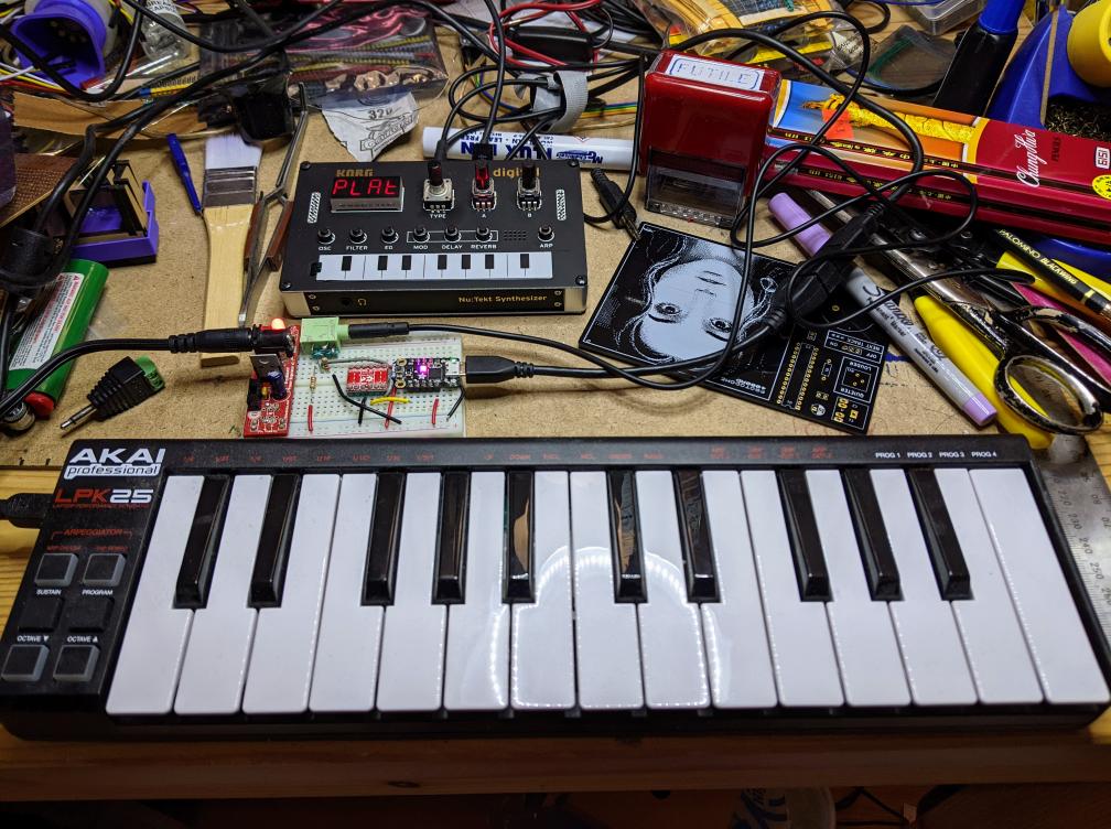
It pleased me to learn about umidiparser – MIDI file parser for Micropython. Could I use my previous adventures in beepy nonsense to turn a simple MIDI file into a terrible squeaky rendition of same? You betcha!
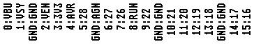
MIDI seems to be absurdly complex. In all the files I looked at, there didn’t seem to be much of a standard in encoding whether the note duration was in the NOTE_ON event or the NOTE_OFF event. Eventually, I managed to fudge a tiny single channel file that had acceptable note durations in the NOTE_OFF events. Here is the file:
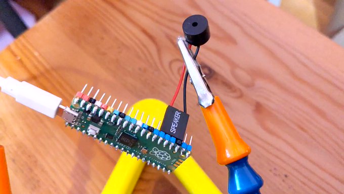
I used the same setup as before:
With this code:
# extremely crude MicroPython MIDI demo
# MicroPython / Raspberry Pi Pico - scruss, 2022-08
# see https://github.com/bixb922/umidiparser

import umidiparser
from time import sleep_us
from machine import Pin, PWM

# pin 26 - GP20; just the right distance from GND at pin 23
#  to use one of those PC beepers with the 4-pin headers
pwm = PWM(Pin(20))
led = Pin('LED', Pin.OUT)


def play_tone(freq, usec):
    # play RTTL/midi notes, also flash onboard LED
    # original idea thanks to
    #   https://github.com/dhylands/upy-rtttl
    print('freq = {:6.1f} usec = {:6.1f}'.format(freq, usec))
    if freq > 0:
        pwm.freq(int(freq))       # Set frequency
        pwm.duty_u16(32767)       # 50% duty cycle
    led.on()
    sleep_us(int(0.9 * usec))     # Play for a number of usec
    pwm.duty_u16(0)               # Stop playing for gap between notes
    led.off()
    sleep_us(int(0.1 * usec))     # Pause for a number of usec


# map MIDI notes (0-127) to frequencies. Note 69 is 440 Hz ('A4')
freqs = [440 * 2**((float(x) - 69) / 12) for x in range(128)]

for event in umidiparser.MidiFile("lg2.mid", reuse_event_object=True):
    if event.status == umidiparser.NOTE_OFF and event.channel == 0:
        play_tone(freqs[event.note], event.delta_us)
This isn’t be any means a general MIDI parser, but is rather specialized to play monophonic tunes on channel 0. The result is gloriously awful:
More Micropython programmers — and especially beginners — should know about Awesome MicroPython. It’s a community-curated list of remarkably decent MicroPython libraries, frameworks, software and resources. If you need to interface to a sensor, look there first.
For example, take the INA219 High Side DC Current Sensor. It’s an I²C sensor able to measure up to 26 V, ±3.2 A. It does this by measuring the voltage across a 0.1 ohm precision shunt resistor with its built-in 12-bit ADC. I got a customer return from the store that was cosmetically damaged but still usable, so I thought I’d try it with the simplest module I could find in Awesome MicroPython and see how well it worked.
I guess I needed a test circuit too. Using all of what was immediately handy — a resistor I found on the bench and measured at 150.2 ohm — I came up with this barely useful circuit:

The INA219 would be happier with a much higher current to measure, but I didn’t have anything handy that could do that.
Looking in Awesome MicroPython’s Current section, I found robert-hh/INA219: INA219 Micropython driver. It doesn’t have much (okay, any) documentation, but it’s a very small module and the code is easy enough to follow. I put the ina219.py module file into the /lib folder of a WeAct Studio RP2040 board, and wrote the following code:
# INA219 demo - uses https://github.com/robert-hh/INA219

from machine import Pin, I2C
import ina219

i = I2C(0, scl=Pin(5), sda=Pin(4))
print("I2C Bus Scan: ", i.scan(), "\n")

sensor = ina219.INA219(i)
sensor.set_calibration_16V_400mA()

# my test circuit is 3V3 supply through 150.2 ohm resistor
r_1 = 150.2
r_s = 0.1  # shunt resistor on INA219 board

# current is returned in milliamps
print("Current       / mA: %8.3f" % (sensor.current))
# shunt_voltage is returned in volts
print("Shunt voltage / mV: %8.3f" % (sensor.shunt_voltage * 1000))
# estimate supply voltage from known resistance * sensed current
print("3V3 (sensed)  / mV: %8.3f" % ((r_1 + r_s) * sensor.current))
with everything wired up like this (Blue = SDA, Yellow = SCL):
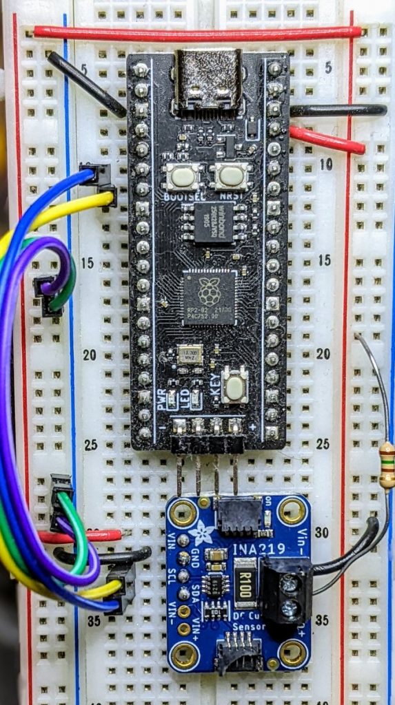
Running it produced this:
I2C Bus Scan:  [64]

Current       / mA:   22.100
Shunt voltage / mV:    2.210
3V3 (sensed)  / mV: 3321.630
So it’s showing just over 22 mA: pretty close to what I calculated!
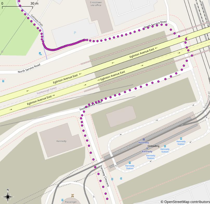
It feels like forever, but it was probably 2018 that the roads through Kennedy Station were closed to dig the huge hole for the Eglinton Crosstown. So for all that time, I’ve been braving the deadly intersection at Kennedy and Eglinton to get back home from my daily bike ride.
But as of late last week, the roads reopened and I’ve been enjoying the wheee! instead of constant fear of dying. There’s still some work needed, so it’s not all sunbeams and cucumbers:
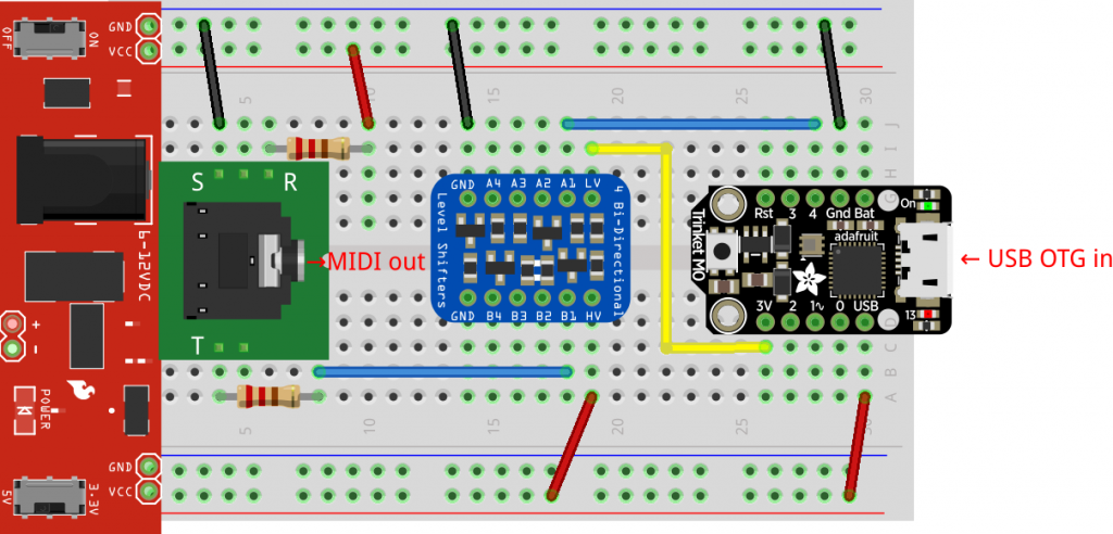
This is great: gdsports/midiuartusbh: MIDI DIN to MIDI USB Host Converter allows your USB MIDI instruments to act as traditional MIDI controllers. It uses a Adafruit Trinket M0 to act as the USB host and MIDI output.
I modified gdsports’ design very slightly:
And it works!
In early 2013, I must’ve been left unsupervised for too long since I made The Quite Rubbish Clock:
Written in (Owen Wilson voice) kind of an obsolete vernacular and running on hardware that’s now best described as “quaint”, it was still absurdly popular at the time. Raspberry Pis were still pretty new, and people were looking for different things to do with them.
I happened across the JASchilz/uQR: QR Code Generator for MicroPython the other day, and remembered I had some tiny OLED screens that were about the same resolution as the old Nokia I’d used in 2013. I wondered: could I …?
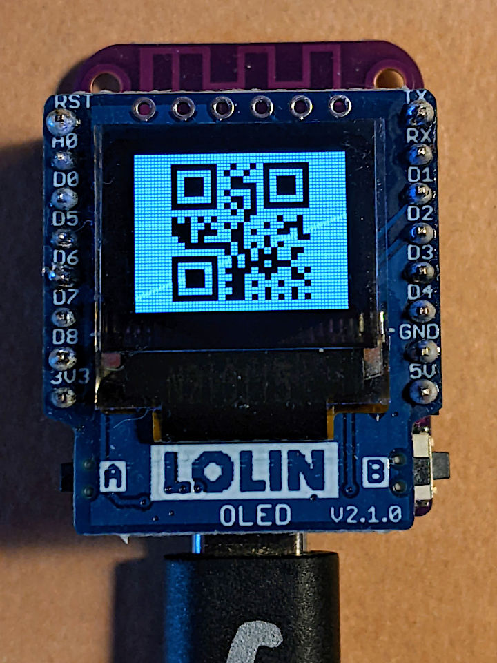
The board is a LOLIN S2 Mini with a OLED 0.66 Inch Shield on top, all running MicroPython. One limitation I found in the MicroPython QR library was that it was very picky about input formats, so it only displays the time as HHMMSS with no separators.
Source, of course:
# -*- coding: utf-8 -*-
# yes, the Quite Rubbish Clock rides again ...
# scruss, 2022-06-30
# MicroPython on Lolin S2 Mini with 64 x 48 OLED display
# uses uQR from https://github.com/JASchilz/uQR
# - which has problems detecting times with colons

from machine import Pin, I2C, RTC
import s2mini  # on Lolin ESP32-S2 Mini
import ssd1306
from uQR import QRCode

WIDTH = 64  # screen size
HEIGHT = 48
SIZE = 8  # text size
r = RTC()

# set up and clear screen
i2c = I2C(0, scl=Pin(s2mini.I2C_SCL), sda=Pin(s2mini.I2C_SDA))
oled = ssd1306.SSD1306_I2C(WIDTH, HEIGHT, i2c)
oled.fill(0)


def snazz():
    marquee = [
        "   **",
        "   **",
        "   **",
        "   **",
        "   **",
        "********",
        " ******",
        "  ****",
        "   **",
        " quite",
        "rubbish",
        " clock",
        "  mk.2",
        "<scruss>",
        " >2022<"
    ]
    for s in marquee:
        oled.scroll(0, -SIZE)  # scroll up one text line
        oled.fill_rect(0, HEIGHT-SIZE, WIDTH,
                       SIZE, 0)  # blank last line
        oled.text("%-8s" % s, 0, HEIGHT-SIZE)  # write text
        oled.show()
        time.sleep(0.25)
    time.sleep(5)
    oled.fill(1)
    oled.show()


snazz()  # tedious crowd-pleasing intro

qr = QRCode()
while True:
    qr.add_data("%02d%02d%02d" % r.datetime()[4:7])
    qr.border = 1  # default border too big to fit small screen
    m = qr.get_matrix()
    oled.fill(1)
    for y in range(len(m)):
        for x in range(len(m[0])):
            # plot a double-sized QR code, centred, inverted
            oled.fill_rect(9 + 2*x, 1 + 2*y, 2, 2, not m[y][x])
    oled.show()
    time.sleep(0.05)
    qr.clear()
If your output is glitchy, you might need to put the following in boot.py:
import machine
machine.freq(240000000)
This increases the ESP32-S2’s frequency from 160 to 240 MHz.

The Internet Archive has Threlkeld Granite Co Ltd’s Album of ornamental granitic tiles online, and I’m really digging the patterns of the hydraulic tiles they made. I’ve recreated some of their patterns in InkScape, and made this small demo by tiling bitmapped renderings.
Rob Cruickshank noted the other day:
Naturally, I had to verify this. So I tuned to the WWV 10 MHz time signal on my amateur rig, tuned a portable radio to CBC Radio 1 FM, which broadcasts on 99.1 MHz in Toronto and recorded them together:
Yup: Rob’s right – CBC is broadcasting the NRC 13:00:00 signal at 13:00:10, which for time nerds might as well be the change from Julian to the Gregorian calendar.
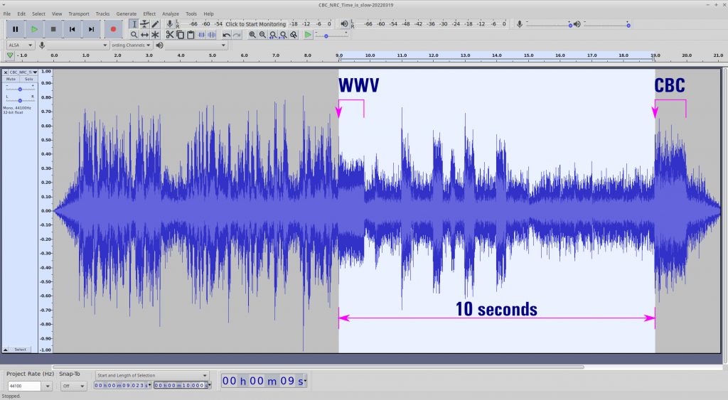
This recording was made directly from the airwaves. There should be effectively no difference between the signal broadcast times, but here we are with the “National Research Council official time signal” going out at a very wrong time indeed.
Update, October 2023: Well, CBC has noticed, and rather than trying to fix it, they’re going to end it: The end of the long dash: CBC stops broadcasting official time signal | CBC News
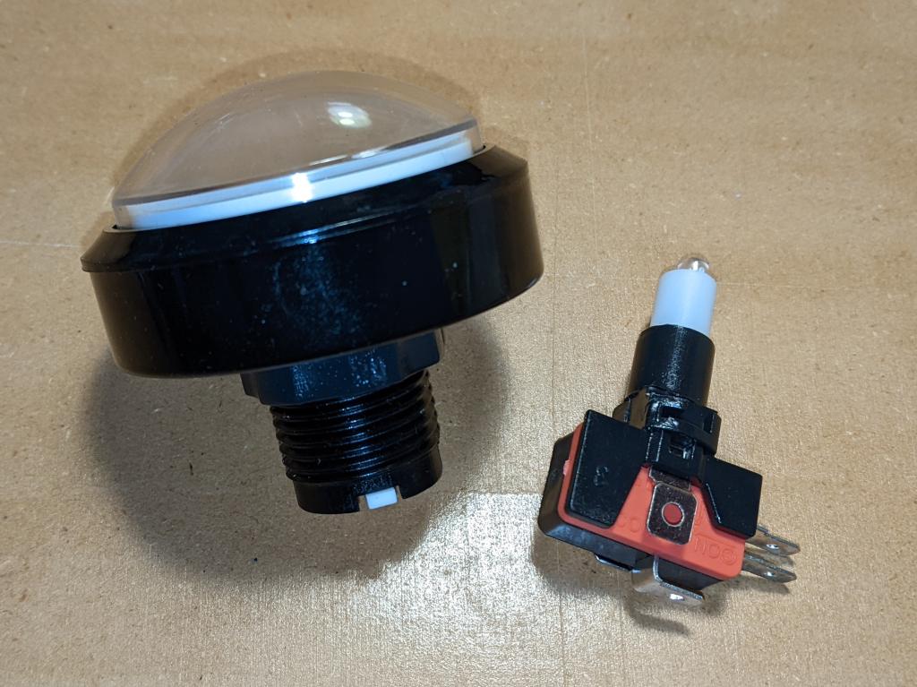
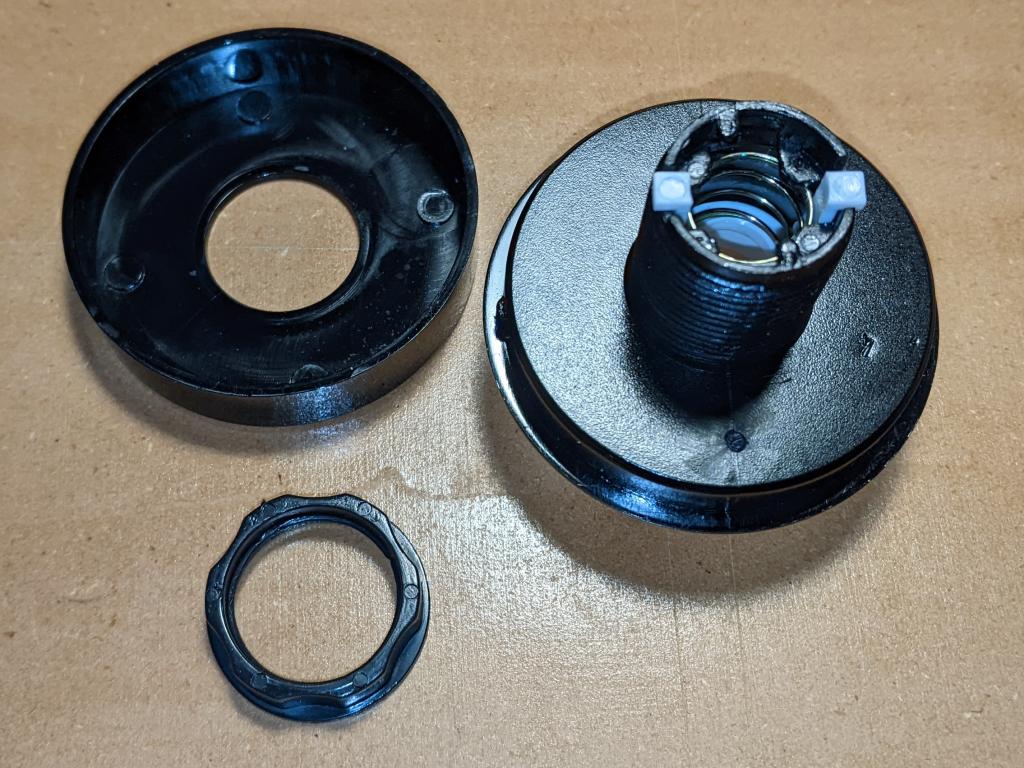
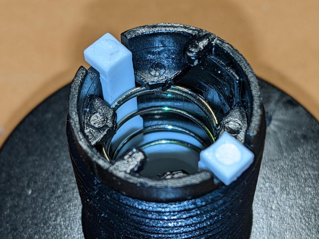
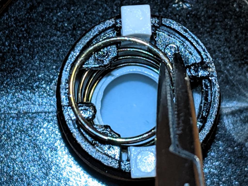
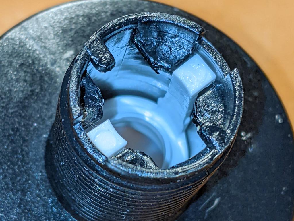
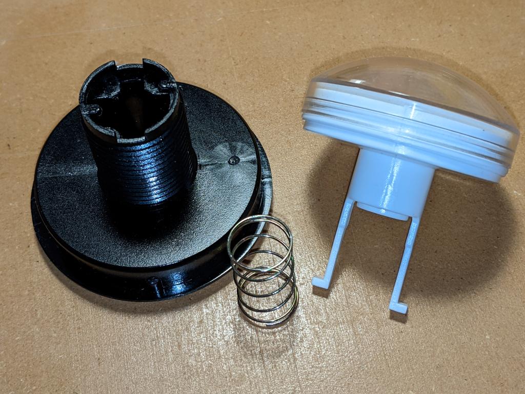
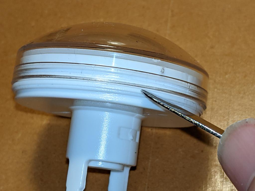
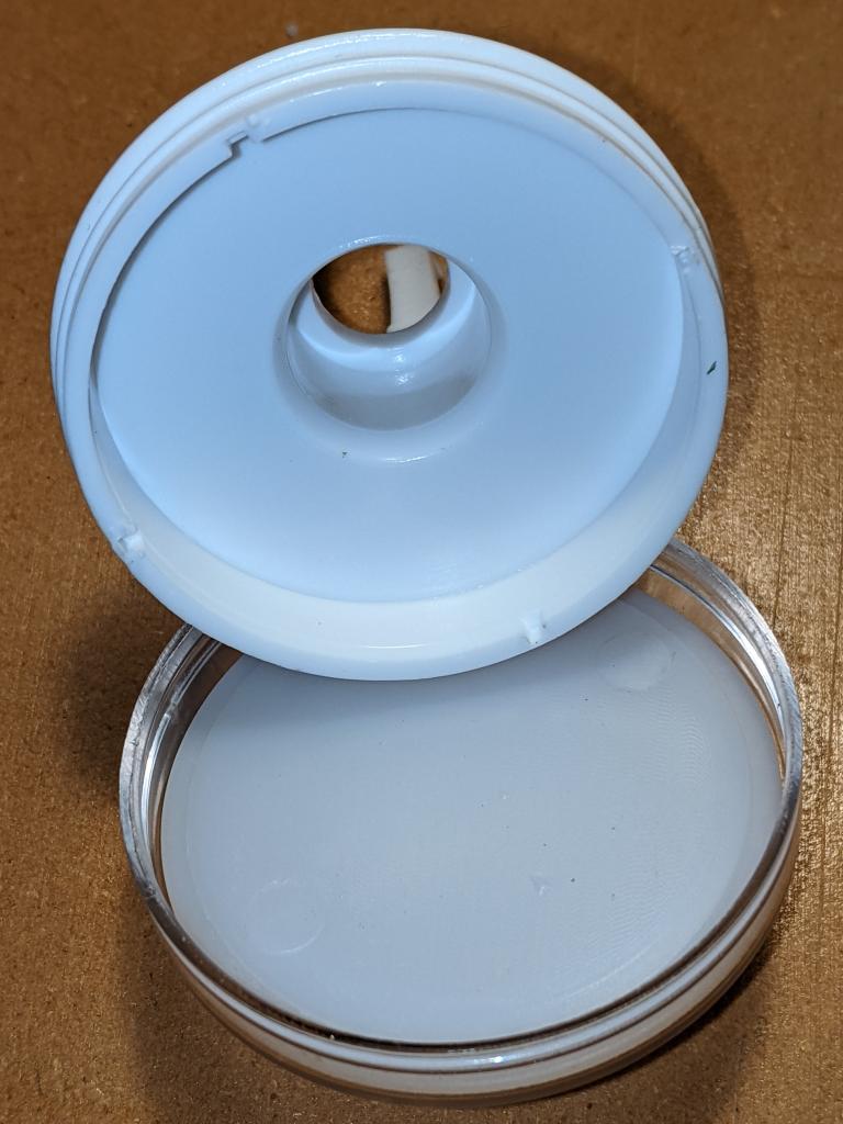
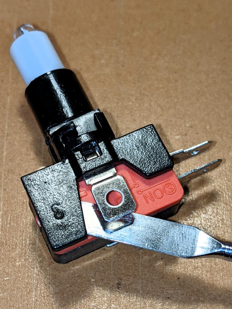
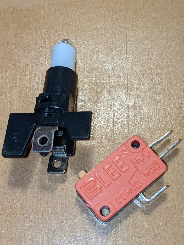
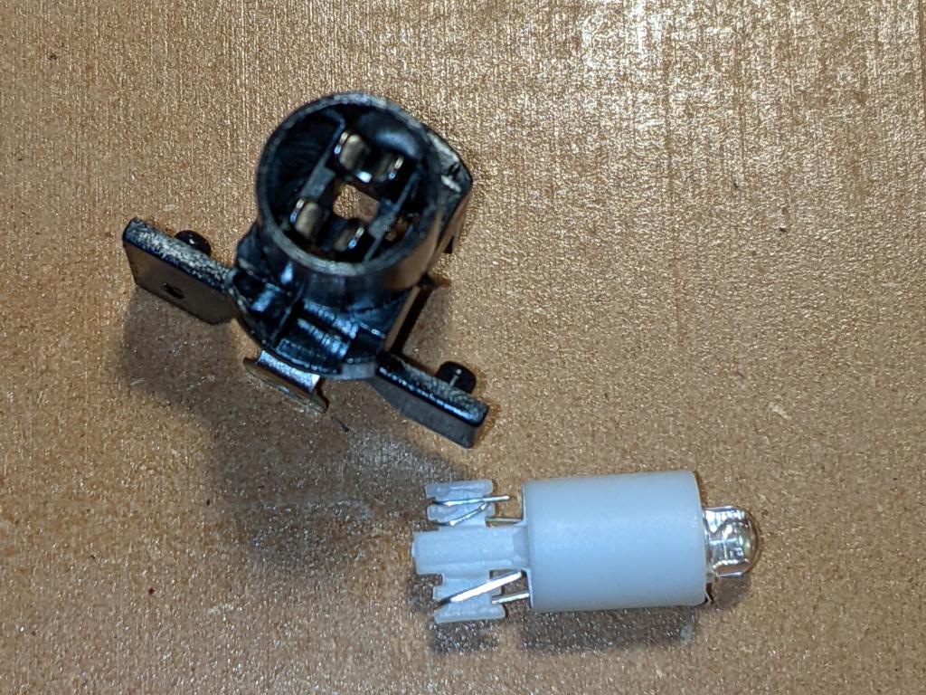
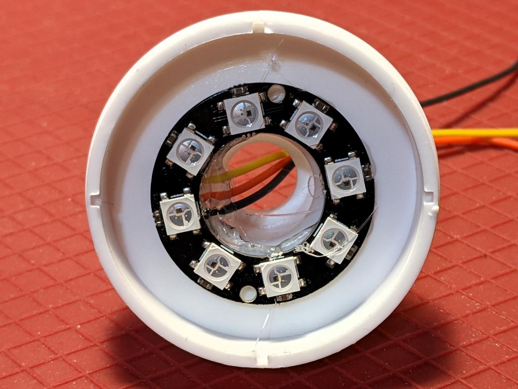
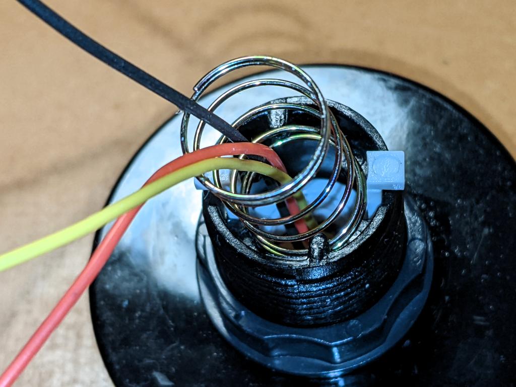
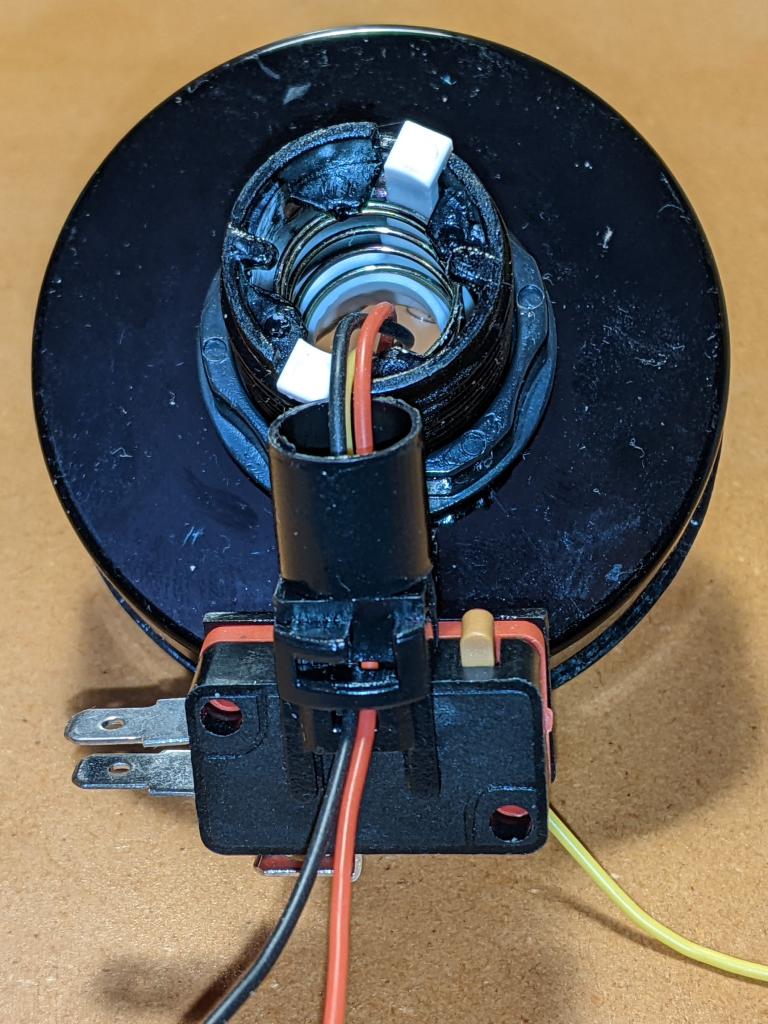
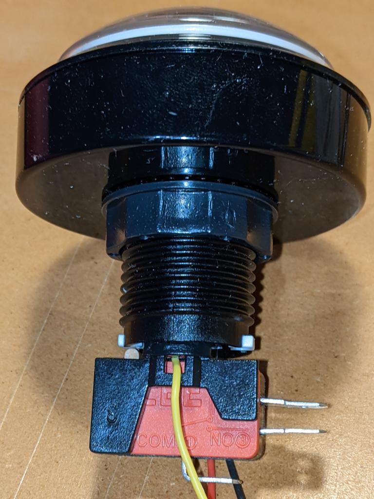
Following on from a customer query at Elmwood Electronics, I can confirm that one can install install addressable RGB LEDs/NeoPixels inside one of these large buttons. It’s not the easiest build, so whether one should attempt this is another matter entirely.
You’ll need:
I’m not going to cover soldering the wires to the LED PCB in any depth here. You’ll need three wires: 5 V power, Ground and Data. Even though the LEDs I used need 5 V power, they are quite happy with 3.3 V logic on the data line. They need more than 3.3 V power to light, though.

PDF, too, if you like such things: record_label_jali.pdf. Made with OpenSCAD.
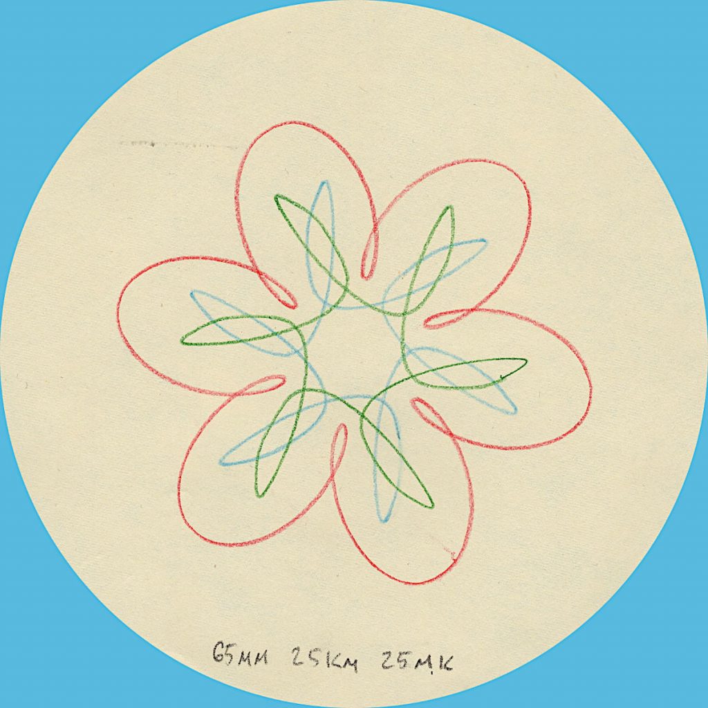
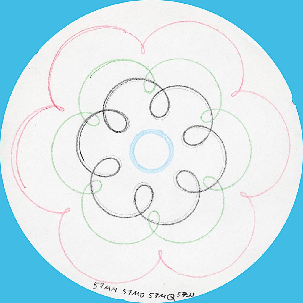
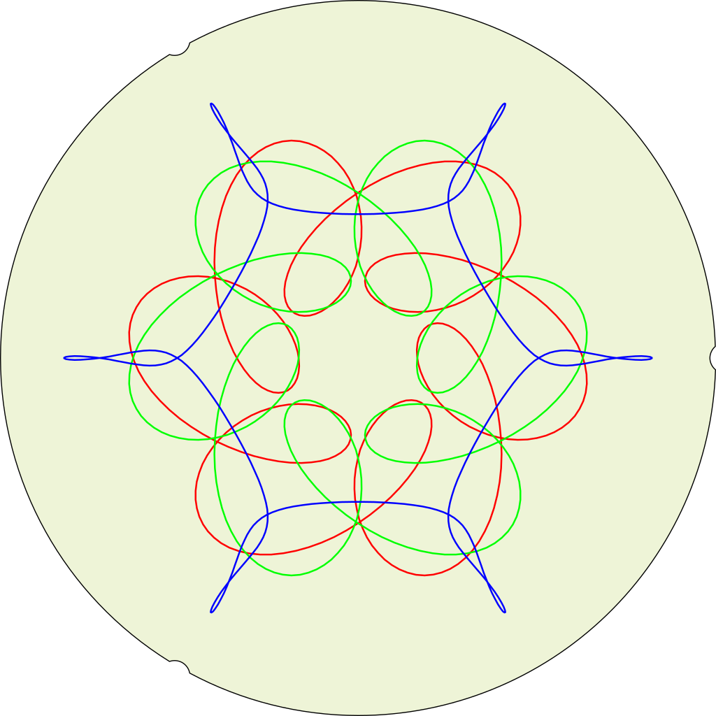
Simulated (and not quite right yet) output from a “HOOT-NANNY” or Magic Designer, a proto-Spirograph toy that drew six-sided curves on round paper sheets. It was made by Howard B. Jones and Co. of Chicago, IL and first sold in 1929. The company’s better known for producing Jones Plugs and Sockets, sometimes known as Cinch-Jones connectors. The “HOOT-NANNY” name was dropped when production moved to the Northern Signal Company of Saukville, WI.
My eBay-acquired Magic Designer is quite beaten up, and doesn’t always produce accurate results. Here’s how one should look, from the instruction pamphlet:
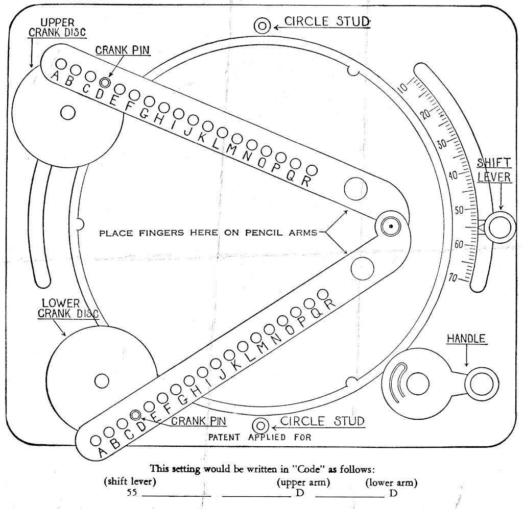
As far as I’ve been able to work out, the parameters of the machine are:
If we model the toy with a fixed turntable:
Here’s a very simple model in Python that emits a hard-coded (but editable) pattern in HP-GL: Slightly imperfect Python simulation of the “HOOT-NANNY” (or Magic Designer) drawing toy (static local copy: hootnanny.zip). It doesn’t do anything with the fixed circle studs (yet)
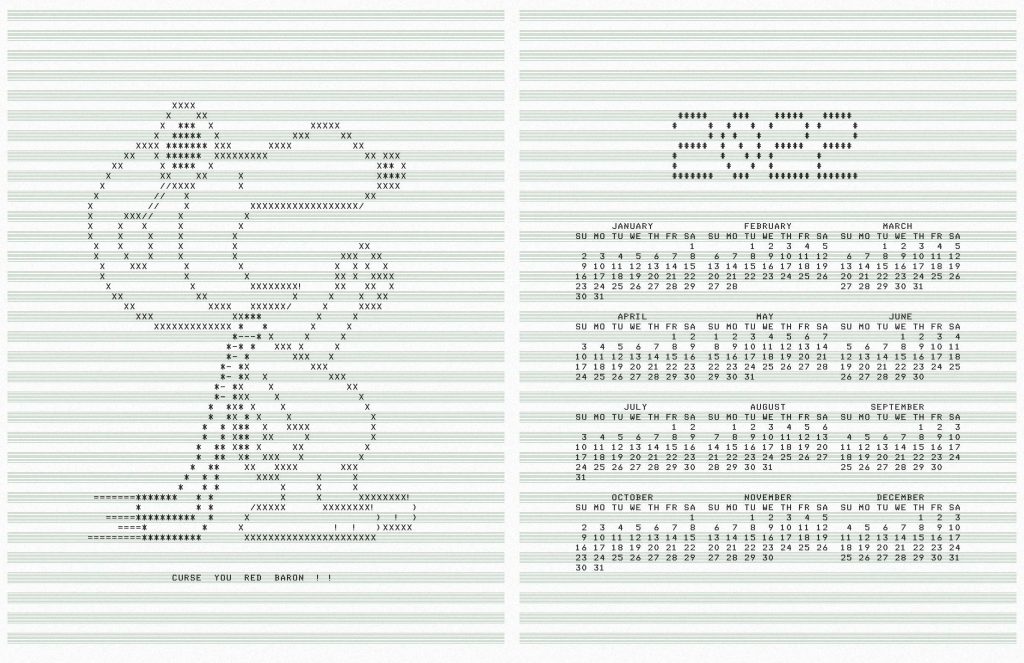
It’s unlikely anyone wanted a faux-lineprinter ASCII art calendar for 2022, but you’re getting one anyway. You can print this yourself:
If you want to make your own, here’s a script: snoopycal.sh
Credits:
Something has gone very wrong with the database encoding on this blog after a recent update, so all my lovely UTF-8 characters have gone mojibake.
Trying to find ways to fix it. It may have to be manual. Remember, kids: have backups before letting WordPress upgrade!
Here’s the Python equivalent of what I think the database has done:
bytes("I ???? UTF-8", encoding='utf-8').decode(encoding='cp1252')
'I 💔 UTF-8'
Quite why my hosting thought a character encoding from last century was appropriate, I’ll never know.
Update, November 2023: kinda-sort fixed the backend, but the encoding is still weird — can we…?

… only to realize I don’t really like circular key grids.

So I ported autumn in canada from OpenProcessing to PicoMite BASIC on the Raspberry Pi Pico:
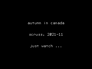
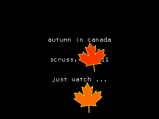
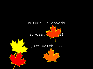
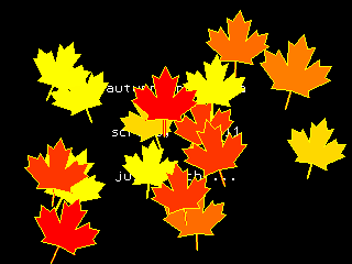

The biggest thing that tripped me up was that PicoMite BASIC starts arrays at 0. OPTION BASE 1 fixes that oversight. It would have been nice to have OpenProcessing’s HSV colour space, and an editor that could handle lines longer than 80 characters that didn’t threaten to bomb out if you hit the End key, but it’ll serve.
Source below:
' autumn in canada
' scruss, 2021-11
' a take on my https://openprocessing.org/sketch/995420 for picomite

OPTION base 1
RANDOMIZE TIMER
' *** initialize polar coords of leaf polygon and colour array
DIM leaf_rad(24), leaf_ang(24), px%(24), py%(24)
FOR i=1 TO 24
    READ leaf_rad(i)
NEXT i
FOR i=1 TO 24
    READ x
    leaf_ang(i)=RAD(x)
NEXT i

DIM integer c%(8)
FOR i=1 TO 8
    READ r%, g%, b%
    c%(i)=RGB(r%,g%,b%)
NEXT i

' *** set up some limits
min_scale%=INT(MIN(MM.HRES, MM.VRES)/8)
max_scale%=INT(MIN(MM.HRES, MM.VRES)/6)
min_angle=-30
max_angle=30
min_x%=min_scale%
min_y%=min_x%
max_x%=MM.HRES - min_x%
max_y%=MM.VRES - min_y%

CLS
TEXT MM.HRES/2, INT(MM.VRES/3), "autumn in canada", "CM"
TEXT MM.HRES/2, INT(MM.VRES/2), "scruss, 2021-11", "CM"
TEXT MM.HRES/2, INT(2*MM.VRES/3), "just watch ...", "CM"

kt%=0
DO
    cx% = min_x% + INT(RND * (max_x% - min_x%))
    cy% = min_y% + INT(RND * (max_y% - min_y%))
    angle = min_angle + RND * (max_angle - min_angle)
    sc% = min_scale% + INT(RND * (max_scale% - min_scale%))
    col% = 1 + INT(RND * 7)
    leaf cx%, cy%, sc%, angle, c%(7), c%(col%)
    kt% = kt% + 1
LOOP UNTIL kt% >= 1024

END

SUB leaf x%, y%, scale%, angle, outline%, fill%
    FOR i=1 TO 24
        px%(i) = INT(x% + scale% * leaf_rad(i) * COS(RAD(angle)+leaf_ang(i)))
        py%(i) = INT(y% - scale% * leaf_rad(i) * SIN(RAD(angle)+leaf_ang(i)))
    NEXT i
    POLYGON 24, px%(), py%(), outline%, fill%
END SUB

' radii
DATA 0.536, 0.744, 0.608, 0.850, 0.719
DATA 0.836, 0.565, 0.589, 0.211, 0.660, 0.515
DATA 0.801, 0.515, 0.660, 0.211, 0.589, 0.565
DATA 0.836, 0.719, 0.850, 0.608, 0.744, 0.536, 1.000
' angles
DATA 270.000, 307.249, 312.110, 353.267, 356.540
DATA 16.530, 18.774, 33.215, 3.497, 60.659, 72.514
DATA 90.000, 107.486, 119.341, 176.503, 146.785, 161.226
DATA 163.470, 183.460, 186.733, 227.890, 232.751, 270.000, 270.000
' leaf colours
DATA 255,0,0, 255,36,0, 255,72,0, 255,109,0
DATA 255,145,0, 255,182,0, 255,218,0, 255,255,0
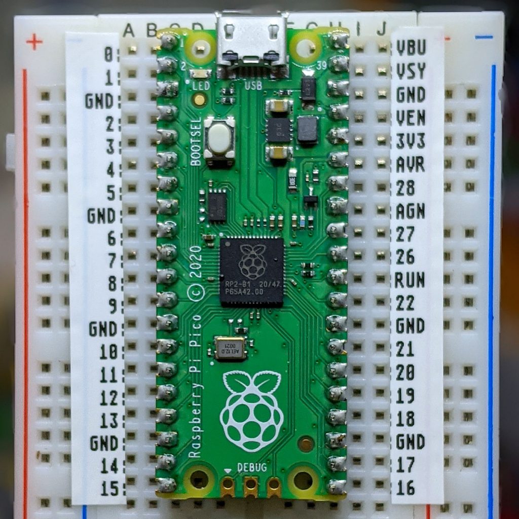
You could probably use AUTOSAVE and paste the text into the PicoMite REPL. I used an ILI9341 SPI TFT LCD Touch Panel with my Raspberry Pi Pico along with some rather messy breadboard wiring.
Fun fact: the maple leaf polygon points are derived from the official definition of the flag of Canada.
This worked better than I expected. The tricky parts are trimming the edges and getting it them straight.
Here’s the image to print on your label maker: