
Instagram filter used: Sutro
Hey! This article is really old. The advice given here will not work on a Raspberry Pi 3, and will need some care with recent versions of Raspbian.
Sometimes you find a computer component that’s so cheap, that works so well, that you’re amazed you managed to live without it for so long. The JY-MCU Arduino Bluetooth Wireless Serial Port Module is that component for me right now.
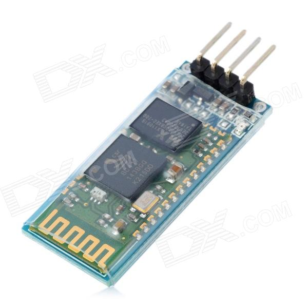
This little board is a cheap ($8.50!) Bluetooth serial port. It’s happy with the Raspberry Pi’s 3.3 V logic levels, and will communicate at standard rates between 1200 and 1,382,400 baud. It even comes with a nifty little cable which is just the right polarity for the Raspberry Pi’s GPIO pins. It’s really meant to do serial comms on an Arduino, but it’s not limited to that.
What this board allows you to do is connect to your Raspberry Pi’s serial console via Bluetooth. That way, you can have your Raspberry Pi hidden away somewhere, and yet still log in as if you were talking to it directly through a serial cable. Combine this with a USB wireless adaptor (like the Belkin N150 that I use) and you’ve got a wireless device you can always connect to, even if your network goes down.
In order to use this device with your Raspberry Pi, you’re going to have to do some reconfiguration. Exactly what reconfiguration you do depends on some additional hardware:
(I chose this option, as it allows me to use the Bluetooth module with Firmata on an Arduino, too.)
The JY-MCU board comes with no instructions, but all the reconfiguration commands you’ll need are explained here: hc06_linvor_1.5_at_command_set [[hc06_linvor_1.5_at_command_set]] (cached copy; original has gone) While you’re setting the communications speed, you’ll probably also want to change the device name (so you can more easily recognize your own board, as the default is something like “Linvor”) and PIN (for that warm feeling of security that only a four digit code can provide). The device is configured using AT commands (or as we eldsters call them, Hayes commands) by plugging it directly into a USB-TTL Serial device attached to your computer. Here’s how you wire it:
USB-TTL Serial    Bluetooth Serial
================= =================
GND               GND
VCC               VCC
TXD               RXD
RXD               TXD
Note that TXD and RXD are crossed. The Bluetooth unit runs on a 3.6-6V supply, but 3.3V logic. To enter the AT commands, start a serial terminal (Hyperterm, minicom, screen …) at 9600 baud talking to the USB-Serial adapter, and copy and paste these commands in:
AT+NAMEBluey
AT+PIN4321
AT+BAUD8
You’ll have to disconnect the terminal and reconnect at 115,200 baud, as that last command just reset the Bluetooth device’s speed. You might want to use other settings than Bluey for the name and 4321 for the PIN, too.
Update: check that your Raspberry Pi’s /boot/cmdline.txt contains:
console=ttyAMA0,115200
You will not get a login prompt otherwise.
Now go to Using the Device.
Serial terminals traditionally ran at 9600 baud, and that seems a bit slow these days. But, if you don’t have a way of setting up the Bluetooth device differently, 9600 is what you’re stuck with. You’ll need to edit your Raspberry Pi’s /boot/cmdline.txt so that the part that previously read:
console=ttyAMA0,115200 kgdboc=ttyAMA0,115200
to
console=ttyAMA0,9600 kgdboc=ttyAMA0,9600
Note that this file should only contain one line, so be careful you don’t add extra line breaks or your Raspberry Pi won’t boot. Save the file, reboot your Raspberry Pi, and go to the next section.
Using the Device
On your Raspberry Pi, connect the Bluetooth Wireless Serial Port Module as follows:
Raspberry Pi      Bluetooth Serial
================= =================
5V  (GPIO Pin  2) VCC
GND (GPIO Pin  6) GND
TXD (GPIO Pin  8) RXD
RXD (GPIO Pin 10) TXD
(Despite the minimum 3.6V rating, I’m happily running mine from the 3V3 power, GPIO Pin 1. YMMV.)
When the board gets power, but isn’t paired, the LEDs on the Bluetooth module flash quickly. Now you need to pair the device with your computer (use 0000 as the PIN, or whatever you chose if you changed it), and it will appear as a serial port on your machine. On my Mac, that’s a device called /dev/tty.Bluey-DevB. The LEDs stop flashing when the port goes into use. Open up a serial terminal, set the device and speed correctly, and if all goes well, you should see:
Debian GNU/Linux wheezy/sid raspberrypi ttyAMA0

raspberrypi login:
Success!

archived from MP3: Black Walls — Gabriel’s Message | Silent Shout — Canadian indie electronic music blog and Toronto DJ night as the original SoundCloud link is gone.
I never quite get the hang of setting timers for lights. Either I forget daylight savings completely, or I set something so general that I find the lights coming on mid-afternoon when it’s still light. Minor annoyances require the over-application of technology, and fast!
I scored an X10 ActiveHome Starter Kit for cheap(ish) on eBay. X10 is a pretty old technology (1970s! Scottish!) and has some severe limitations (slow! prone to interference! unencrypted!) but has a large user base, and did I mention it’s pretty cheap?
The key component of a computer controlled X10 system is the CM11 computer interface. It takes serial commands from a computer, and pushes them out (slowly) as signals modulated over your house wiring. Various plug-in modules pick up these signals, and if the device address in the command matches that of the module, the module turns on (or off, or dims).
Since the version of the CM11 interface that I have is serial, I’ll need a USB→Serial converter. All I had lying around was a very old Prolific PL2303 interface, which works fine with Raspbian, but I’d prefer an FTDI one for more reliability. Long-term stability of USB Serial on the Raspberry Pi is currently questionable; there’s some good discussion on kernel parameters that might help.
To send X10 commands from a Raspberry Pi (or indeed, any Linux computer) you need heyu. You have to build it from source, but the instructions are clear, and it takes about 10 minutes to build on a 256 MB Raspberry Pi. The install script asks you where your serial port is, and for my device it is /dev/ttyUSB0.
(Update: I re-imaged the Raspberry Pi that runs these tasks today and rebuilt heyu without success. Don’t assume you can do a ./configure; make; sudo make install here. You have to run heyu’s own ./Configure.sh first before make. It does some non-obvious magic. Read the README and you’ll be fine, unlike me …)
Most of the lights in our house are fluorescent, which is a problem for the standard X10 lamp modules. CFLs are not dimmable, and the standard lamp module doesn’t work with them. The lamp modules don’t work very well with low-voltage halogen lamps, either; extreme buzzing ensues, with a faint brownish light oozing out from the bulb and a vague burning smell. Best avoided, and better to use an appliance module, which is a simple mechanical relay.
The only controller that came with the kit that would work with my lights was the X10 transceiver, which also includes an appliance switch. I gave this device an address of H9 (house code H, unit code 9), and plugged in a lamp. To turn it on, I issued this command:
heyu on H9
After about 8-10 a couple of seconds and a loud CLUNK from the controller’s relay, the light came on (if it’s taking longer, read this comment). To turn it off, I told it:
heyu off H9
Whoa! Raw power! I can now turn AC devices on and off from my Raspberry Pi (Martin Creed, watch out!). I guess I could set up cron jobs to control the lights, but cron doesn’t know about solar time (Sunwait and SunCron do, if you want to futz with them). I’ve got MisterHouse running on the Raspberry Pi for more clever control, but more on setting that up later.
Incidentally, if you’re in Europe, Marmitek sell a variety of 220 V 50 Hz X10 modules. Their website is much clearer than the angry-fruit-salad that is x10.com. It looks like X10 have updated their starter kit to include the newer CM15 USB interface which will likely not work with heyu.
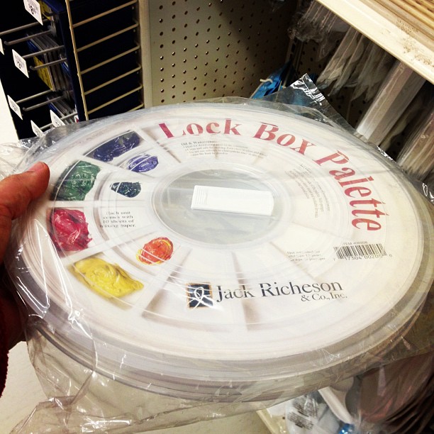
You have to be of a certain age to recognize this:

… not just as an artist’s travel palette, but as a repurposed case for a 9-track tape spool. While tape drives were iconic for mainframe computers (so much so, there’s a Unicode glyph for them: ✇), the last drives and tapes came off the line a decade ago. They’re not truly dead until everybody forgets what these cases were originally for.
This is my profile on Microsoft’s new social thing, socl:
 Every link produces no content, and the name looks suspiciously like “sod” if over-kerned. Well, at least it’ll make Google+ feel busy.
I can’t seem to do anything; creating a post gives me this:

Sorry, folks at 10 PRINT, I think the Amstrad CPC’s version simply pwns the C64:
;: GOTO 10")
what did the farmer say when he lost his tractor?
where’s my tractor?
why is it when a old man with one kid people thinks ”stranger”, but when its a old man with 20 kids people think ”school trip” . im on to you old people
Q) why did’nt the man clime up the mountain
A) because there wasn’t a mountain
— from Bad Kids Jokes (via)